

1. 概述
本文講述如何搭建 S32G-VNP-RDB3 M 核和 A 核雙核工作環境。
2. 構建 Cortex-A53 核代碼
2.1 配置交叉編譯器
下載適用於ARM 64位的GCC 10.2.0工具鏈(下載鏈接)。
放在工作目錄下解壓:
$tar -xf gcc-arm-10.2-2020.11-x86_64-aarch64-none-linux-gnu.tar.xz
2.2 編譯 uboot
下載 uboot 源碼:
$export HOME=/path/to/your/workspace
$cd $HOME
$git clone https://source.codeaurora.org/external/autobsps32/u-boot
$cd u-boot
$git checkout release/bsp35.0-2020.04
編譯 uboot:
$export CROSS_COMPILE=$HOME/gcc-arm-10.2-2020.11-x86_64-aarch64-none-linuxgnu/bin/aarch64-none-linux-gnu-
$make s32g399ardb3_defconfig
$make
2.3 編譯 ATF
安裝軟體:
$sudo apt-get install libssl-dev openssl
安裝/升級到dtc 1.4.6或更高版本:
$dtc –version
$sudo apt-get install device-tree-compiler
獲取 ATF 源碼:
$cd $HOME
$git clone https://source.codeaurora.org/external/autobsps32/arm-trusted-firmware
$cd arm-trusted-firmware
$git checkout release/bsp35.0-2.5
修改如下:
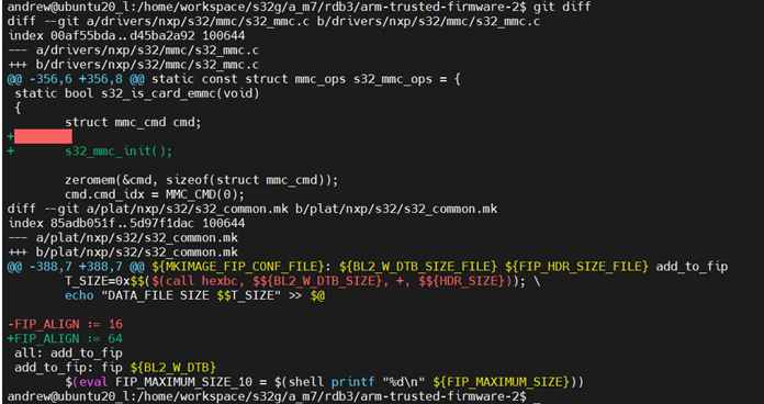
編譯 ATF:
$make ARCH=aarch64 PLAT=s32g399ardb3 BL33=$HOME/u-boot-2/u-boot-nodtb.bin
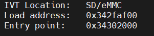
構建完成後,生成的圖像位於目錄中:arm trustedfirmware/build/s32g274ardb2/release。日誌顯示了生成的FIP映像的加載地址和入口點,如下所示:
2.4 編譯linux
$cd $HOME
$git clone https://source.codeaurora.org/external/autobsps32/linux
$cd linux
$git checkout release/bsp35.0-5.10.145-rt
$make ARCH=arm64 s32cc_defconfig
$make ARCH=arm64
2.5 編譯 IPC
獲取 IPC 源碼:
$cd $HOME
$git clone https://source.codeaurora.org/external/autobsps32/ipcf/ipc-shm
$cd ipc-shm
$git checkout release/SW32G_IPCF_4.8.0_D2212
編譯:
$cd $HOME
$make -C ./ipc-shm/sample_multi_instance KERNELDIR=$PWD/linux modules
2.6 製作 SD 卡
搭建 ycoto 工程,如所示,
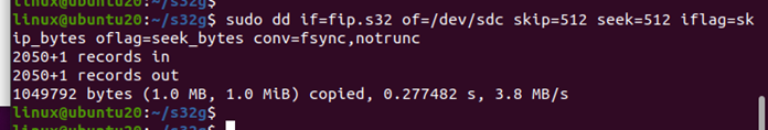
燒錄 yocto 鏡像包到 SD 卡,然後燒錄替換 bootloader:
$ dd if=fip.s32 of=/dev/sdb skip=512 seek=512 iflag=skip_bytes oflag=seek_bytes conv=fsync,notrunc
拷貝 linux/arch/arm64/boot/Image 和 linux/arch/arm64/boot/dts/freescale/s32g399a-rdb3.dtb 到 SD 卡的 boot 分區。
拷貝 ipc-shm/ipc-shm-dev.ko 和ipcshm/sample_multi_instance/ipc-shm-sample_multi-instance.ko 到 SD 卡 root 分區。
3. 構建 M7 和代碼
3.1 安裝配置 S32 Design studio
下載S32 Design Studio 3.5並完成安裝:
S32DS.3.5_b220726_win32.x86_64.exe
SW32G_S32DS_3.5.1_D2210.zip
按照步驟為S32DS安裝RTD和IPCF包:
① 下載RTD版本:SW32G_RTD_4.4_4.0.0_P05_HF01_D2305_DS_updatesite.zip
② 啟動S32DS 點擊 Help > `Install New Software…`. 在安裝界面, 點擊 `Add…`> `Archive…` 打開 SW32G_RTD_4.4_4.0.0_P05_HF01_D2305_DS_updatesite.zip. 點擊打開進行安裝,下面軟體也是一樣操作的方法:
SW32G_IPCF_4.8.0_D2212_updatesite.zip
SW32_FreeRTOS_10_4_6_UOS_4_0_2_DS_updatesite_D2307.zip
SW32G_SDHC_1_0_4_D2310_updatesite.zip
③ 編譯 M7_0 代碼
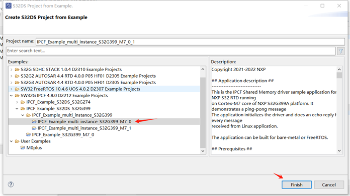
點擊 file -> New -> S32DS Project from Example。
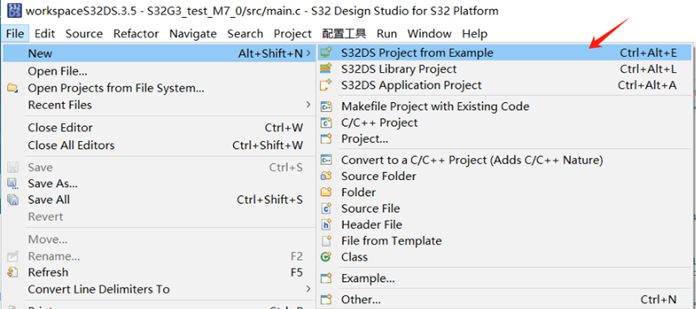
找到 IPCF_Example_multi_instance_S32G399_M7_0 工程並點擊 Finish。
3.2 配置 bootloader
① 下載 EB::
Nxp 官網下載EB tresos Studio 29.0.0 的 EBtresosStudio_EBtresosStudio.zip,放到工作目錄下解壓使用。
② 安裝 RTD 軟體:
下載 SW32G_RTD_4.4_4.0.0_P05_HF01_D2305.exe
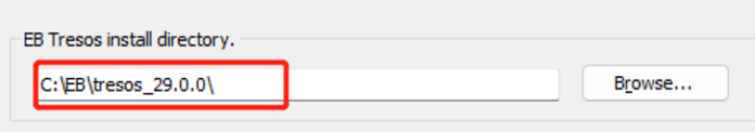
需要配置 EB 路徑,如下所示:
③ 安裝 Integration_Reference_Examples 軟體:
下載Platform_Software_Integration_S32G3_2023_02.exe
安裝時也需要配置 EB 路徑,如下所示:

④ 配置EB 工程
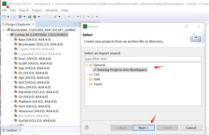
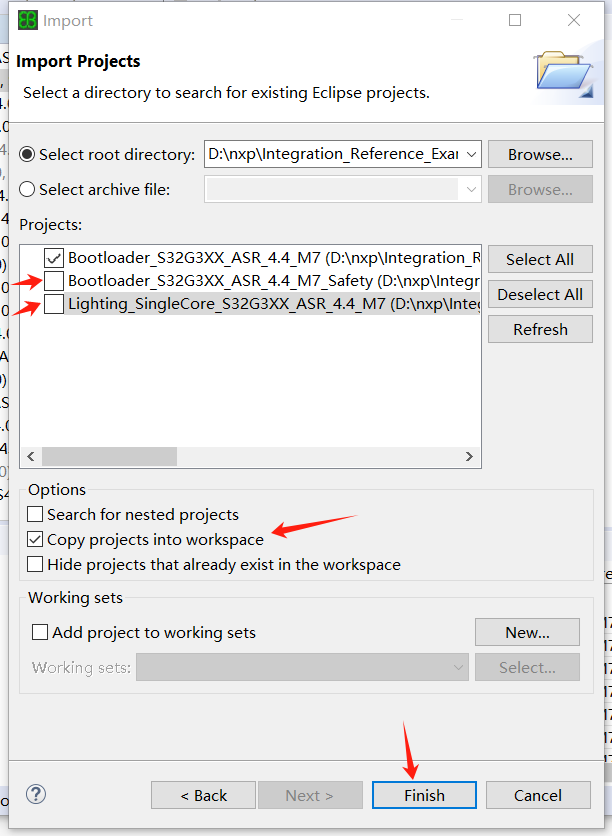
點擊 tresos_gui.exe 打開軟體,點擊 file -> Import… -> 選擇 General -> 點擊 Existing Projects into Workspace -> 點擊 Next。
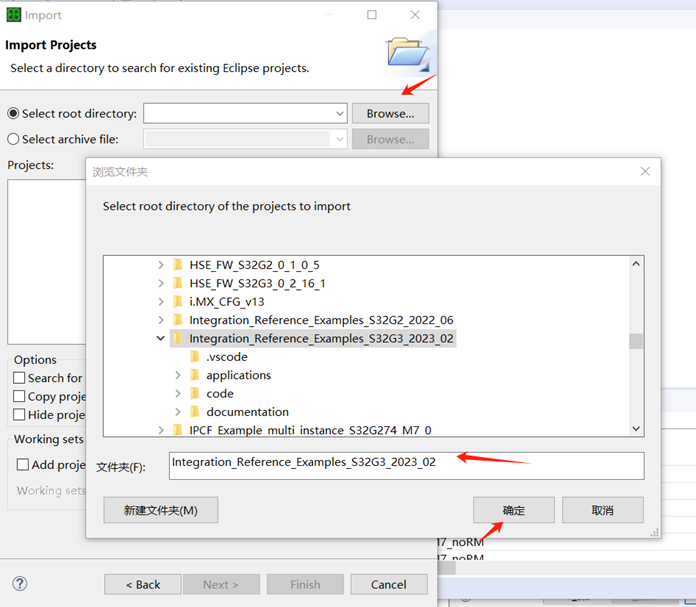
點擊 Browse… -> 找到 Integration_Reference_Examples_S32G3_2023_02 安裝目錄 -> 點擊確定。
只選擇第一個工程配置 -> 勾選 Copy peojects into wrokspace -> 點擊完成。
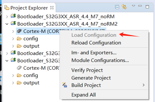
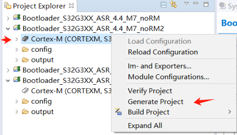
右擊工程 Cortex-M -> 點擊 Load Configuration。
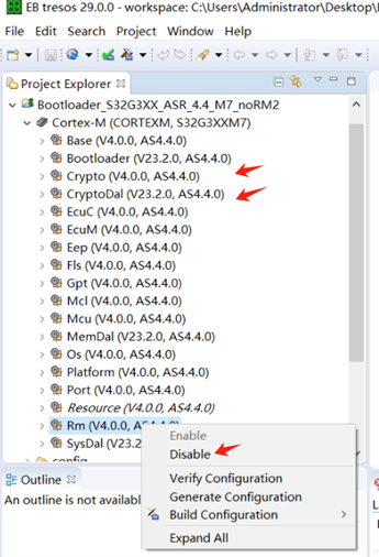
分別右擊 RM、Crypto 和CryptoDal,都 disabled 掉。
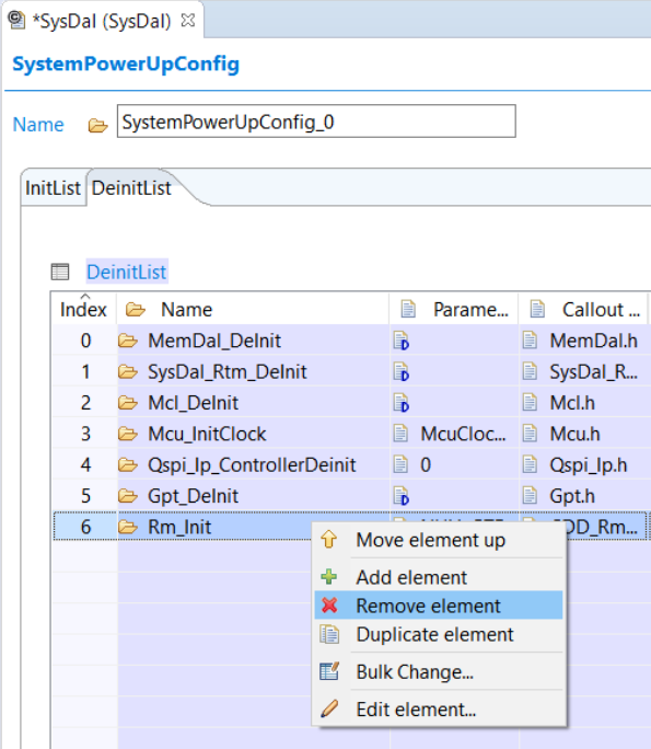
導航到SysDal插件配置,選擇SysDalBswConfig ->PowerUp ->DeinList 。在列表中,刪除項目Rm_Init。
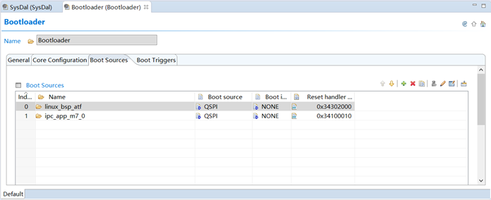
導航到Bootloader插件的配置。選擇“Boot Sources”,配置 linux_bsp_atf 和 ipc_app_m7_0 如下所示:
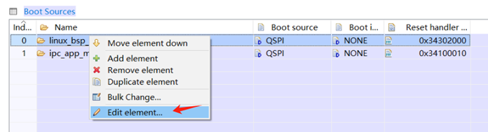
分別右擊 linux_bsp_atf 和 ipc_app_m7_0 打開 Edit element… 配置。
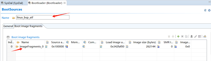
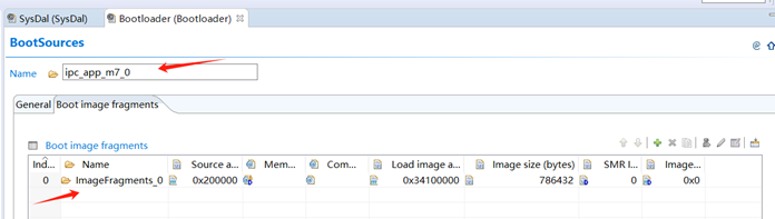
分別配置如下所示:
右擊 Cortex-M 選擇 Generate Project。成功生成後,單擊“確定”完成。
⑤ 構建 Bootloader
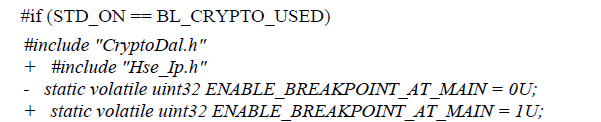
修改 D:\nxp\Integration_Reference_Examples_S32G3_2023_02\code\framework\realtime\swc\bootloader\generic\src\ Bootloader.c 文件:
配置D:\nxp\Integration_Reference_Examples_S32G3_2023_02\code\framework\realtime\swc\bootloader\platforms\S32G3XX\build\configuration.bat 文件:
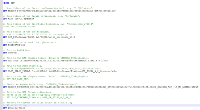
去掉 RM、Crypto 和 CrcytoDal 相關的 .c 和 .h 文件,打開電腦 cmd 命令行,進入 D:\nxp\Integration_Reference_Examples_S32G3_2023_02\code\framework\realtime\swc\bootloader\platforms\S32G3XX\build\ 目錄,執行 launch.bat 命令編譯
⑥ 配置 S32DS IVT_TOOL
打開一個工程,打開工程的 IVT 配置,Boot Target 選擇 M7_0,QuadSPI parameters 選擇
D:\nxp\Integration_Reference_Examples_S32G3_2023_02\code\framework\realtime\swc\bootloader\platforms\S32G3XX\res\flash\S32G3XX_QuadSPI_133MHz_DDR_configuration.bin 文件。
DCD 選擇 D:\nxp\Integration_Reference_Examples_S32G3_2023_02\code\framework\realtime\swc\bootloader\platforms\S32G3XX\res\flash\S32G3XX_DCD_InitSRAM.bin 文件。
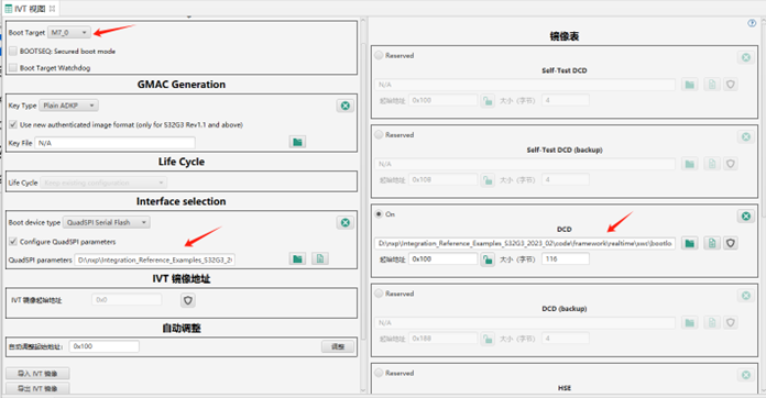
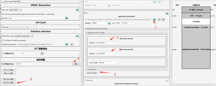
操作圖示如下:
1 -> 選擇文件:D:\nxp\Integration_Reference_Examples_S32G3_2023_02\code\framework\realtime\swc\bootloader\platforms\S32G3XX\build\bin\Bootloader.bin;
2 & 3 –> 輸入地址 0x35300000;
4 -> 輸入自動調整起始地址,並點擊調整;
5 -> 導出 Image 並命名 bt_m7_app.bin;
6 -> 導出 Blob 鏡像並命名 bt_m7_blob.bin。
4. 在s32g-vnp-rdb3上部署
以下是使用S32閃存工具對Nor閃存進行編程的步驟。
① 在目錄中啟動S32 Flash工具:
D:\NXP\S32DS.3.5\S32DS\tools\S32FlashTool\GUI\s32ft.exe
② 將 RDB3 UART0 連接到 PC USB 埠,配置如下: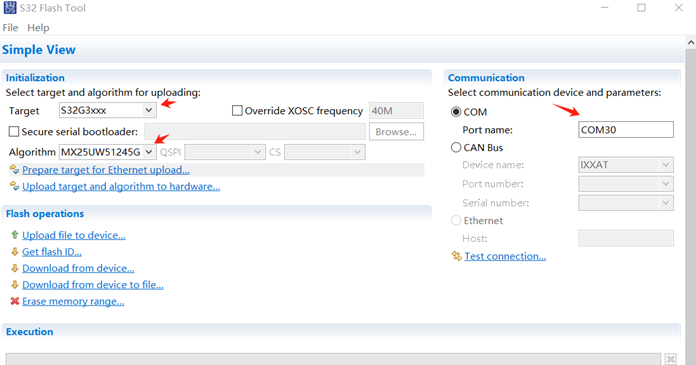
④ 打開RDB3 的電源。
⑤ 點擊 “Upload target and algorithm to hardware…”
⑥ 點擊 `Erase memory range…` 並擦除內存範圍 0x0 - 0x500000.
⑦ 點擊 `Upload file to device…` ,選擇 bt_m7_blob.bin 寫到地址 0x0.
⑧ 點擊 `Upload file to device…` ,選擇 fip.bin 寫到地址 0x100000
⑨ 點擊 `Upload file to device…`,選擇 IPCF_Example_multi_instance_S32G274_M7_0.bin 文件燒錄到地址 0x200000。
5. 在S32G-VNP-RDB3上運行應用程序
以下是在S32G2 RDB2板上運行應用程序的步驟
① 將SD卡插入RDB3的插槽。
② 將RDB3 配置從外部 NOR-Flash 啟動模式
SW10-1=ON,SW10-2=OFF
SW4 all OFF
③ 將RDB2 UART0連接到PC USB埠4。
④ 在PC上啟動串行終端,用波特率115200設置串行埠,格式8-n-1
⑤ 打開RDB3 的電源。如果一切正常,將在終端上獲得A53啟動日誌。
⑥ 配置 bootloader 關掉 PCIE,然後內核啟動後,輸入root登錄。
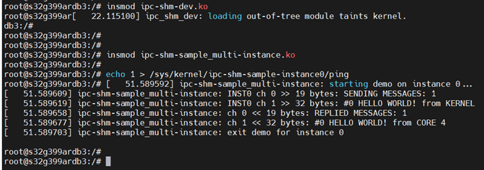
⑦ 掛載 IPC 模塊
$insmod ipc-shm-dev.ko
$insmod ipc-shm-sample_multi-instance.ko
⑧ 運行IPC示例。將看到顯示Linux內核和Cortex-M7內核之間IPC消息的日誌。
$echo 1 > /sys/kernel/ipc-shm-sample-instance0/ping
至此完成搭建 S32G-VNP-RDB3 M 核和 A 核雙核工作環境以及測試!
參考文獻
《AN13750.pdf》
《TP-S32G-VNP-RDB3.pdf》
評論
wzlinux
9 個月前